Final Project
Final Project Idea #1
My first final project idea is to design a train set that will start when someone is within close proximity to the train set. Another student in the class had a similar idea though, so I will brainstorm a different idea.
Final Project Idea #2
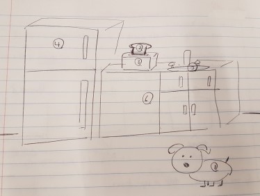
My second final project idea is to make a physical patent map of everyday items, such as toaster and crustless toast, or of Formlabs printer. The purpose of this project would be create an interactive way for people to learn about intellectual property. What I have found is that most people are aware of the patents, but do not know what can be patented. This would be a fun way to educate people on IP.
The big bulk of my project will come from the last few weeks, specifically input devices, networking and communications, and interface and app programming, but here is a brainstorm of what I want to create!
Week 1: Vinyl and Laser Cutting
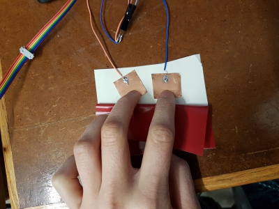
Since I want to use copper pads for capacitance touch, I will likely use vinyl to decorate my final project by placing it on top of the copper pads. I tested my capacitance touch to ensure that there will still be a change in voltage through the vinyl. There is!
I tried making a prototype of the room through laser cutting cardboard. However, my pieces all came out in different sizes and it took me a few tries to figure out why.
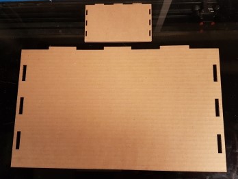
It turned out that zooming in on Rhino changes the size of the piece to be cut. Construction lines from Fusion360 were showing on Rhino so I zoomed in to remove them and it turns out that this is what caused the different sizes. I will keep this in mind as I make my final project!
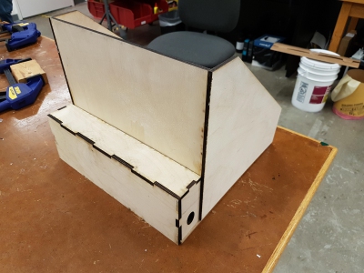
Here is my progress on lasercutting the frame of the room and the sink!

Week 2: Electronics Production
This week is very much integral to my final project as I need to mill and solder circuitboards to run the electronics.
Week 3: 3D Printing and Scanning
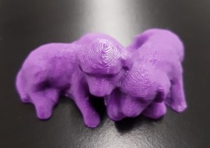
To make objects with great precision, I will use 3D printing. This will mainly be for the dog, since I found it difficult to get details through molding and casting or through composites.
Week 4: Electronics Design
Like Week 2, this week will be critical to my final project as Eagle is used everytime I want to design a circuitboard.
Week 7: Molding and Casting
I first wanted to fabricate these everyday items. This came up initially in Week 7 when I made toast through molding and casting.
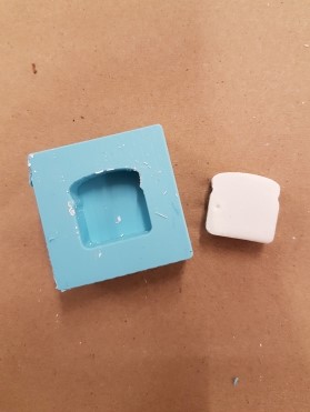
The toast was simple enough to make, though I imagine complications in inserting a button within the toast.
Now that I have capacitance touch working and inspired by Shivaei, I tried inserting copper pads within casts at varying thicknesses. Since I was pouring in the plaster, it was hard to perform this experiment with accuracy, but I attempted to make plasters at 4 different thicknesses.

What I found though was that the copper pads likely moved as I was pouring in the plaster and were too close together. Even without me touching the plaste, the voltage was high.
It seems like the best bet will be to simply put copper pads on top of objects.
Week 8: Output Devices
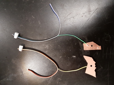
This week I will figure out how to wire external buttons to PCB and how to program multiple buttons to communicate with the same 2 LEDs. These external buttons can be placed inside these everyday items, such as toast. Success!
The next step will be to put the button boards into a toast.
After learning networking and capacitance touch, I realize now that putting copper pads on top of objects will be easier than trying to place buttons within objects. However, I may still try and incorporate LEDs, though this will not be my priority.
Now that I have learnt networking, I may forgo having multiple wires connected to one motherboard as this looks messy.
Week 10: Input Devices
This week I learnt how to do capacitance touch. This is a nice upgrade from buttons!
Week 11: Interface and Application Programming
This week I learnt basic python. Now, I can use python canvases to communicate whether something is patented or not when the voltage is above a certain threshold! I just need to figure out how to edit the canvas to make it look better and to get more content on it.
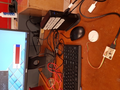
Week 12: Networking and Communications
I further built upon my C and python knowledge by learning how to send serial from circuitboards to the computer when voltage is above a certain threshold, and programming python to read the serial and make canvases depending on serial sent. This will be much easier than connecting multiple circuitboards to different usb ports.
Final Project Idea #3
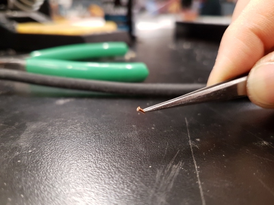
Two days before the final project deadline, I decided to use similar electronics to make an interactive map of Canada instead. The change was mainly for aesthetic reasons, as the kitchen would need to be made up of different materials and it would not look as aesthetically pleasing. Thus, I decided to make this shift to a map of Canada. I had initially thought of making a neighborhood map of Boston but it turns out that there are more neighborhoods of Boston than there are provinces of Canada. My first instinct was to laser cut wood pieces as I had already refamiliarized myself with laser-cutting while attempting to fabricate final project idea #2. However, I found that the copper pads cannot detect the change in voltage under wood, even veneer. While I suspected this may happen as wood is an insulator, I thought that TXRX might be possible if I increased the copper pad sizes, brought them closer together, and used veneer. However, even putting all three factors together, the resulting change in voltage was finicky and the margin of error was too small relative to the change in voltage that needed to be detected. Because of this, I decided to change to load capacitance instead and make my pieces out of double-sided copper sheets and connecting the two sides using copper tape or copper rivets. This would allow me to hide the wires at the back of the copper pads. Before milling though, I made sure that I could use TXRX boards for load capacitance since I had already milled and soldered 7 circuitboads. This seemed like a fairly simple change - instead of sending a serial if difference in voltage was above a certain threshold, I programmed it such that a serial would be sent if the voltage value fellow below a certain threshold value. Or so I thought. I realized the night before the project deadline that you can't simply use a TXRX board for load capacitance. More on this later. Clueless of this fact, I milled some test pieces and tried connecting the two copper sides using copper tape. This was not a strong enough of a connection, and so I tried drilling holes and adding copper rivets. This worked!
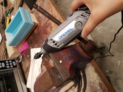
I then finished milling the provinces of Canada and drilled holes into corners of the provinces to solder in copper rivets.
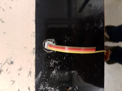
Next step was soldering on wires connected to 2x2 headers. At the same time, GSD was closing for the holidays on Monday at 6pm, so I went to laser cut black acrylic that would form the frame of my project. However, the GSD laser cutters do not identify the origin, so it was hard to cut accurate pieces with my limited supply. Luckily, Daniel Davis came to my rescue and helped me cut in the laser cutter in the science center. Both the cut acrylic and copper provinces can be seen below!

I then drilled holes into the acrylic so that the wires and circuitboards could hide within my acrylic box.
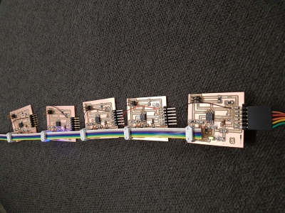
Last but not least, came the electronics. As mentioned before, I thought that I had already finished electronics since each individual province connected to a txrx board appeared to also function as a load capacitance board and I had networked txrx boards before. Turns out it was not so simple. My TXRX board was sensing at PB3 pin, while Neil's program that I based my load capacitance programming on was sensing at PB4 and the GND was connected to different pins. With Rob's help, I manually restructured my circuitboard so that my PB4 was now the sensor. After this, the networking was achieved through bus connection.
Here are my final C file and python.
Below is a picture of my finished product! The video of this working can be found up top.

A lot of thanks to all the TAs that came to my rescue (notably Nathan, Dixon, and especially Kevin for staying in the lab until 5am to help) and Daniel Davis and Rob Hart for the last minute saves!
Materials Used
All the materials I used were from the Harvard lab and the approximated total cost was $66.
| Material | Quantity | Total Cost | |
|---|---|---|---|
| Black acrylic sheet (12"x12") | 1 | $10 | $10 |
| Double-sided copper (100x70mm) | 12 | $1 | $12 |
| Attiny45 | 11 | $0.50 | $5.50 |
| 2x3 header | 22 | $0.50 | $11 |
| 2x2 header | 22 | $0.50 | $11 |
| FTDI | 11 | $0.50 | $5.50 |
| Capacitor | 11 | $0.10 | $1.10 |
| LED | 11 | $0.10 | $1.10 |
| Resistors | 88 | $0.10 | $8.80 |